McDermott Library Guide
Start page
Touching anywhere takes you to the main page (Touch to Begin).

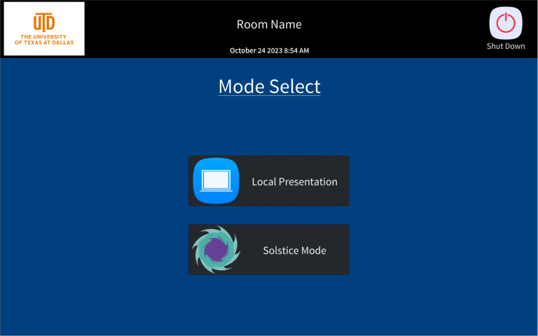
Mode Select
This page is where you can set the system into solstice mode or Local presentation mode. Solstice Mode will automatically the primary solstice pod to all displays. Local Presentation mode provides the flexibility to route any source to any destination without any automatic routing.
Local Presentation
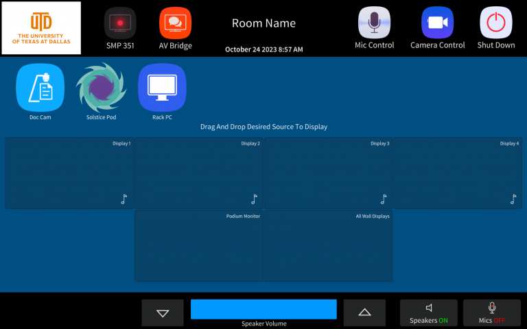
This is the primary page for system use. To utilize the video routing, place your finger on a source and move it to whatever display you wish. The video route will be made, and that video source will be seen on that display. Power and Input settings are handled automatically by the control system.
Along the top of the display, there are different buttons that make popup windows open that you can use to control different aspects of the system. They will be reviewed further down in the documentation.
The music notes are how you indicate which display you are hearing over the speakers in the room. Programmatically, you can only hear one at a time. This is by design.
Basic Volume controls are at the bottom of the display. Volume Up/Down, Speakers On/Off, Mics On/Off. The Mics on/off button is a master kill for all microphones. More finite control of the mics are available in the mic control page.
SMP 351 CONTROLS
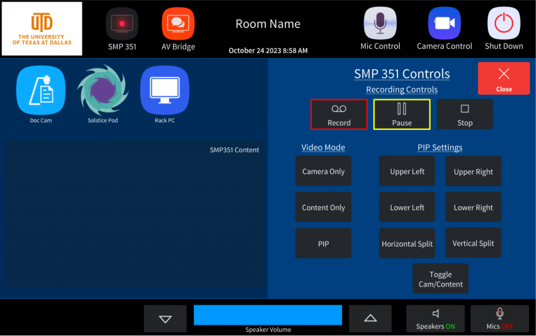
This page is where you control the SMP351 recording device, and is accessed by pressing the “SMP351” button at the top of the page. The Device always received a video feed from the camera, and from a content source that you define on the left of the page. It works the same way that the primary routing does. Put your finger on a source, and drag it to the “Content” box.
On the right hand side of the screen, you can define what is being recorded. The “Camera Only” button full screens the camera, the “Content Only” button full screens the content. The “PIP” button shows both images and allows manipulation of their layouts in the recorder.
The Record button will show a red flashing border when the device is recording (push the button to start recording), the Pause button will show a yellow flashing border when the device recording is paused(push the button to paused recording). Stop Shows nothing and only stops recording when pressed.
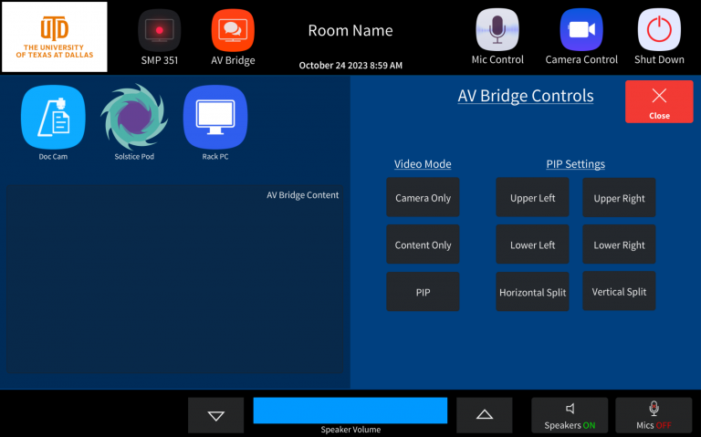
AV BRIDGE CONTROLS
This page is where you control the AV Bridge, and is accessed by pressing the “AV bridge” button at the top of the page. The AV Bridge is the interface for the camera/content directly into the PC.
When you press “Camera Only” The feed is fullscreen camera. When you press “Content Only” the feed is fullscreen Content. PIP Gives you basic controls of the layout of the device video output.
There is no “Swap” feature like the SMP351 controls. Make sure whatever device you want Fullscreen has been selected before pressing the PIP button. For example, if you want the Camera Fullscreen and the content as the PIP image, Press “Camera Only” first, and then the PIP button. You can adjust your layout accordingly after that. You just need to define the fullscreen image first.
MIC SETTINGS
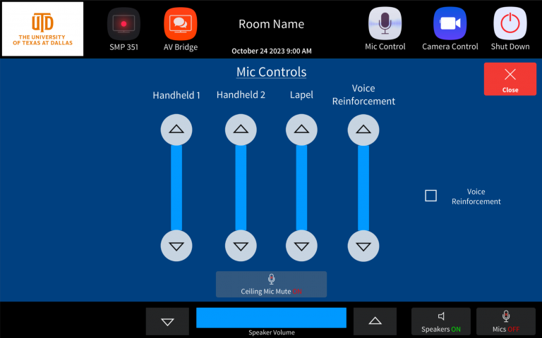
This is the Mic Settings Page, and is accessed by pressing the “Mic Control” button at the top of the page. You can turn the individual microphones up and down here.
You can enable or disable the ceiling microphones on this page also. When the ceiling mic LEDs are RED they are Muted, when they are GREEN they are LIVE. The panel and the mics will stay in sync.
You have the option to turn the Voice reinforcement up and down, on and off on this page. IF the box on the right is checked that says “Voice Reinforcement” it will be enabled.
By default, every time this space goes through the shutdown process, the audio levels will default to a default level. When you start using the system ceiling mics will unmute.
CAMERA CONTROLS
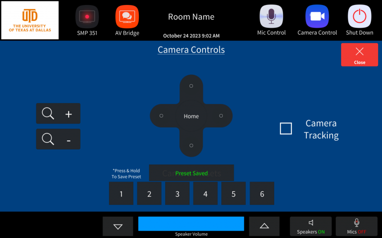
This page allows you adjust the camera image and is access by pressing “Camera Control”.
You can control camera presets at the bottom of the page. It works like a car radio. Tap to recall, Hold to save.
If the camera tracking box is checked, the camera tracking is on and enabled. IT will follow the user walking through the front of the space in front of the camera. It will take 3-5 seconds to enable and disable.
ADMIN SETTING PAGE
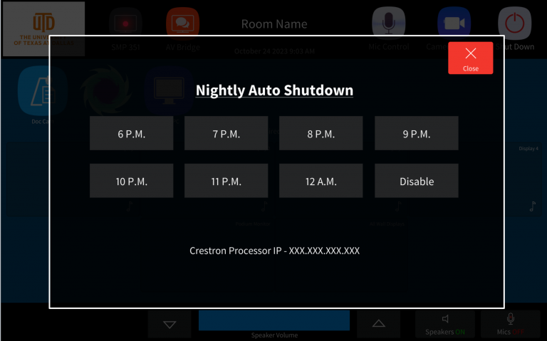
This page is accessed by pressing and holding the UTD logo in the top right corner of the screen for longer than 3 seconds.
The page shows the IP address of the processor and defines the time the system will automatically shut down. You can change this time by simply pressing a different time.
If for example you have 7PM highlighted, at 7PM, the system will go through the shutdown process at 7pm.
